This is an optional hands-on section that will walk-through how to build a Full-Adder in hardware. To follow along you’ll need to have the electronic components and prototyping breadboard available.
74-series Digital Logic Chips
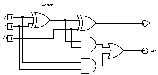
In the last section we learned about the basic digital logic gates: AND, OR, NOT, XOR and others as well as how to assemble a Full-Adder circuit.
While modern consumer hardware, such as computers, phones, TV and so on, utilize custom silicon chips containing millions or billions of such gates, there are also inexpensive chips available for prototyping simple digital logic circuits that have on the order of 4 or 6 gates per chip. In particular, we’ll use the 74-series chips.
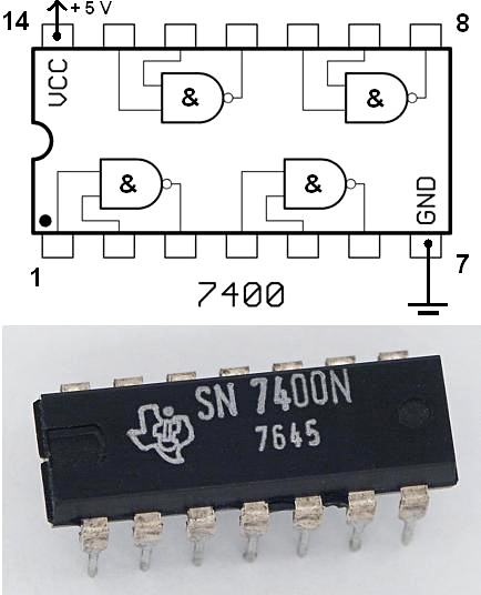
These chips can be identified by having part numbers of the form MM 74XXNNN Z where MM is the manufacturer (e.g. SN or TI for Texas Instruments), XX is a technology family and the NNN (2 or 3 digits) designates the particular functional part - such as the 00 at right designating a quad NAND gate chip with standard pin assignments. We’ll be using the HCT technology family as they provide standard 0V/5V logic voltages for 0/1 (so called, TTL or Transistor-Transistor Logic) and can source enough current to directly drive common LED lights. Hence, we’ll be using the 74HCT86 XOR gate chip, the 74HCT08 AND gate chip and the 74HCT32 OR gate chip to construct our Full Adder circuit.
Full-Adder Prototype Parts List
The full parts list follows, with links to online sources for ordering. Note that the parts are commonly available and you may find them from various sources and as part of larger kits. (For Knoxville, TN, USA residents, Resistors, LEDs, breadboards and wall-plug power supplies are also available locally at Shields Electronics on Middlebrook Pike (click for map) - though at higher prices and with a $20 minimum purchase.)
- 1 x 74HCT86N Quad XOR - Digikey
- 1 x 74HCT08 Quad AND - Digikey
- 1 x 74HCT32 Quad OR - Digikey
- 3 x 1k Ohm resistors Digikey
- 1 x DIP switch (at least 3 switches) - DigiKey
- 2 x LEDs - Digikey (check - unsure of voltage)
- 1 x Prototype breadboard - Digikey
- 1 x Wire interconnects - Digikey
- 1 x 5V regulated DC supply (9-12V input) - Sparkfun
For power, any source of regulated 5V DC power will suffice. Recommend either a Wall-mount adaptor or alternatively a regular rectangle 9V battery. Either:
OR:
- 1 x Wall-mount 9V power supply - Digikey
Assembly
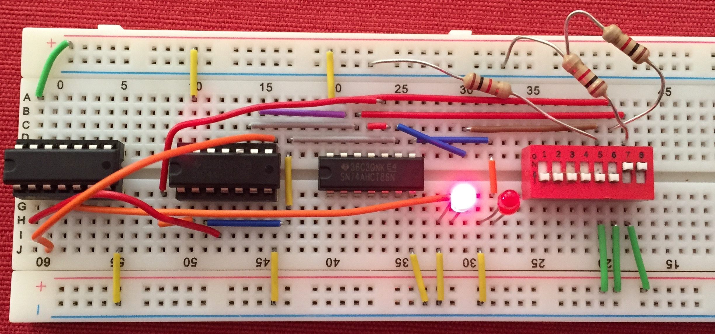
The exact placement of the components on the breadboard isn’t important. Referring to the Full-Adder schematic and to the pin assignments of the chips, we’ll connect the gates so that the circuit is realized. In the picture below, I’ve used mostly stiff wires running along the board for visibility, but it will be easier to use flexible wires (as I’ve done for the connection from J60 to D16 below).
Looking at the breadboard, note that all the pins along a given numbered ‘column’ of the board (across the short axis) are simply connected together, except that there is a division running along the center that divides the board into two disconnected halves. So, all the top half of column 5 are connected together underneath, as are all the hold in the lower half of column 5. In contrast to this vertical interconnection, the board also has two sets of +ve and -ve ‘rails’ running the along the long axis (left to right in the picture) for which the holes are all connected together.
Power
Hence, first connect the 0V/ground/GND of the 5V power supply to the -ve ‘rail’ on either the top or bottom rail and the 5V pins of the power supply to the +ve rail of the board. If you’re using the Sparkfun 5V regulated supply shown in the picture, it has -ve and +ve holes that align with the breadboard rails and all you need to do is connect them through using a jumper wire. Also connect the -ve and +ve rails to their corresponding rail on the lower/upper half. The completes connecting the power supply to the rails.

Inputs
Next, we’ll setup the inputs - in this case, the A, B and Carry-in (Cin) from the circuit to 3 DIP switches (the picture shows an 8-switch DIP package as that’s what I had on hand - hence 5 switches are unused). Place the DIP switch on the right side of the board so that it straddles the midline division - so that the two sides of the switches aren’t just connected together. Now, the switches open or close the circuit through them, but the inputs to the gates on the chips require either ~0V (binary 0) or ~5V (binary 1). So, we need an arrangement whereby they’re connected directly to 5V when the switch is closed, but are ‘pulled down’ to near 0V when the switch is open, using a 1k Ohm pull down resistor connected to 0V (so that closing the switch doesn’t directly connect 0V and 5V and short-circuit the power supply). Hence, connect one side of each of 3 switches to GND/-ve and the other side via a 1K Ohm resistor to the 5V/+ve rail. The resistor side of the switch will connect to the inputs of the gates.
Gate chips
Place the 3 chips we’ll need on the breadboard so that they straddle the midline division, as shown in the picture, the 74xx86 XOR gates on the right, the 74xx08 AND gates in the middle and the 74xx32 OR gates on the left. Ensure the notch in the end of the chips face left. Referring to the chip pin-out diagram of the NAND chip at top (all the chips have the same pins for GND, VCC/+5V and the inputs and outputs of their gates), use jumper wires to connect all the GND pins (bottom left) of the three chips to the lower -ve rail of the board. Similarly, connect all the VCC/5V pins (upper right) of the chips to the upper +ve rail of the board.
The Full-Adder circuit
Go ahead and connect the right-most two switches, we’ll use as A and B, to two inputs of an XOR gate on the 74xx86 chip. Any of the 4 gates on the chip will work, but I chose the gate for which the top left pins next to the power pin are its inputs.
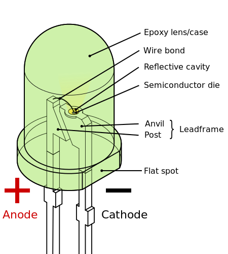
If you’d like to check your circuit functions at this point, you can connect an LED directly to the output pin of the first XOR gate. Notice the LED has a flat side on the body which should be connected to the -ve rail of the breadboard (short lead) with the other, longer, lead connected to the XOR gate output. Try different combinations of the A & B DIP switch inputs to verify it behaves as an XOR gate:
A  B  XOR
0  0  0
0  1  1
1  0  1
1  1  0
As you can see in the circuit, the output of the first XOR gate that A and B connect to, has its output connected to one input of a 2nd XOR gate. Hence, you can use a short wire to directly connect the output pin directly to an input pin of a 2nd XOR gate on the same chip.
By following the wires in the Full-Adder circuit, you can complete the wiring of inputs and intermediate wires on the board.
to be continued…